
Language

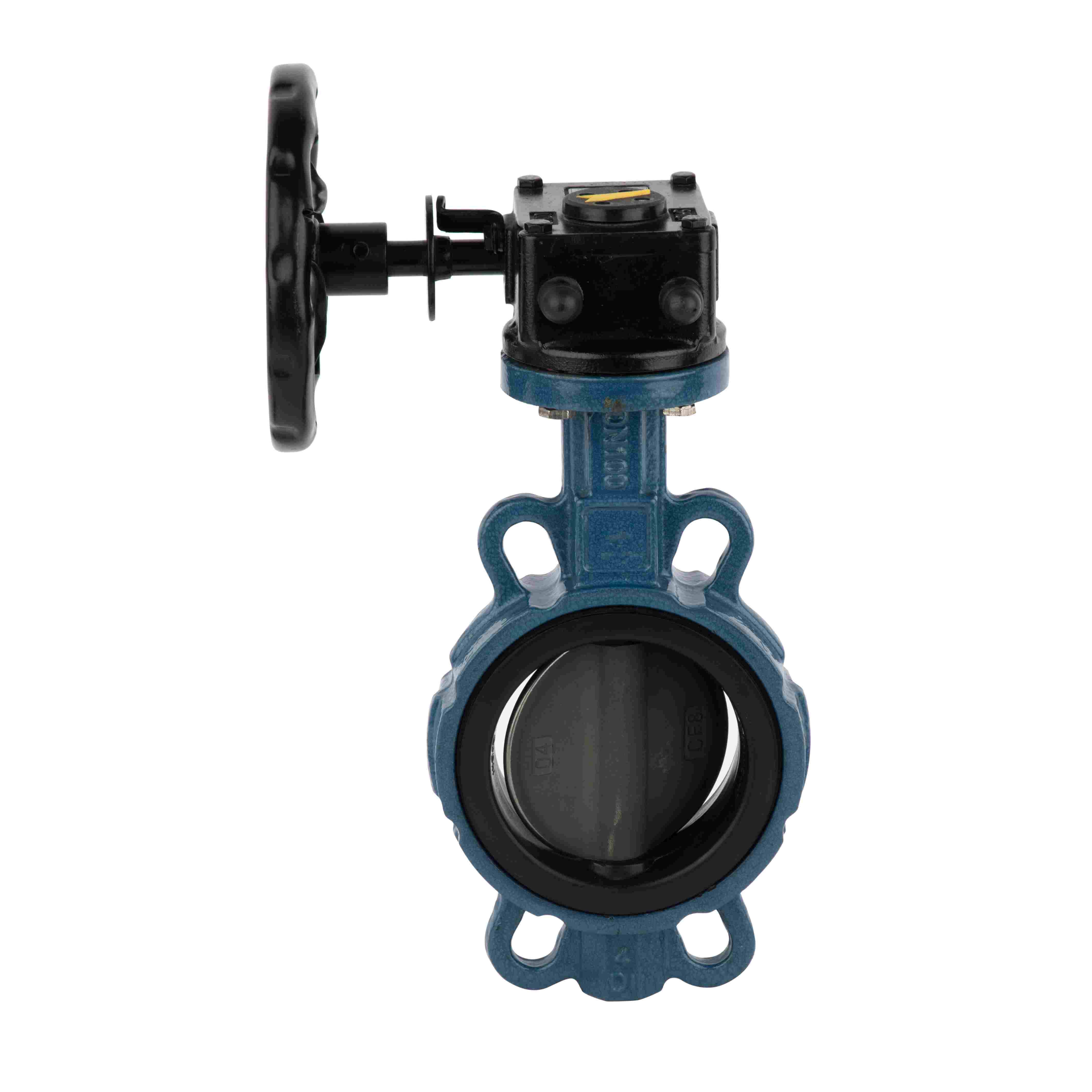
Wafer-type connection is a method of fastening valves (especially butterfly valves, check valves, etc.) between pipe flanges using long bolts. Its defining characteristic is: the valve does not have its own integral flanges; instead, long bolts pass through the flanges of the two pipes to secure the valve in the middle.
Space saving: Wafer valve length (face-to-face dimension) is 1/3 to 1/4 that of a flanged valve.
Cost reduction: Eliminates forging/machining of two integral flanges on the valve body.
Lightweight: Can be handled manually without lifting equipment, especially for large diameters (e.g., DN200 and above).
Cannot be removed independently: To replace a wafer valve, both pipe flanges must be disconnected (i.e., the pipe must be moved apart). Therefore, it cannot be used at pipe dead-ends or where only one side is accessible.
Requires good alignment: Misaligned pipe flanges can twist the valve and cause seal failure.
Not for very high pressure: Typically used in low to medium pressure (≤ PN40 / Class 300); ultra-high pressure may distort the valve body.
Wafer butterfly valves: Water treatment, HVAC, fire protection systems – common due to low cost and easy installation.
Wafer check valves: Prevent backflow; much shorter than swing check valves, clamped directly between flanges.
Wafer lined valves: Corrosion-resistant applications.
Bolt length must be calculated precisely:
2 × pipe flange thickness + valve face-to-face length + 2 × gasket thickness + 2 × nut height
Use appropriate wafer connection standards (e.g., EN 593, API 609, GB/T 12238) with corresponding pipe flange standards (e.g., GB/T 9119, HG/T 20592).
Apply even bolt torque to avoid uneven clamping, which can cause disc binding (a common problem with butterfly valves).
Wafer-type is a connection design aimed at light weight, low cost, and quick installation. It essentially treats the valve as a “clamped component” between two pipe flanges. Selection should consider pressure rating, maintenance access, and removal frequency.


